While sketch was never meant to be a geometric modeling
language, it comes fairly close. The following example puts all we
have seen to work in a very simple model of the human hand. Start by
sweeping a line to make a truncated cone, which will be copied over
and over again to make the segments of fingers.
  def O (0,0,0) % origin
  def I [1,0,0] def J [0,1,0] def K [0,0,1] % canonical unit vectors
  def segment {
    def n_faces 8
    sweep { n_faces<>, rotate(360 / n_faces, [J]) }
      line(proximal_rad, 0)(distal_rad, distal_len)
  }
In hand anatomy, distal is “at the tip” and proximal
is “in the area of the palm.” We have omitted all the scalar
constants. You can find them in hand.sk, which is provided
in the sketch distribution.
We also need a prototypical sphere to use for the joints themselves.
  def joint_sphere {
    def n_joint_faces 8
    sweep [fillcolor=red] { n_joint_faces, rotate(360 / n_joint_faces, [J]) }
      sweep { n_joint_faces, rotate(180 / n_joint_faces) }
        (0, -joint_rad)
  }
We'll now design the index finger (number 1 in our notational convention; finger 0 is the thumb). The distal rotation for the finger applies only to the tip, so we define the following.
  def distal_1 {
    put { translate(joint_gap * joint_rad * [J])
          then rotate(distal_1_rot, [I])
          then translate((distal_len + joint_gap * joint_rad) * [J]) }
      {segment}
    put { rotate(distal_1_rot / 2, [I])
          then translate((distal_len + joint_gap * joint_rad) * [J]) }
      {joint_sphere}
    put { scale( [J] + proximal_distal_ratio * ([I]+[K]) ) }
      {segment}
  }
The identifiers here are for size and location constants. The
exception is distal_rot_1. This rotation parameter models the
flexing of the finger tip. The first put makes a copy of the
finger segment that is translated upward
just far enough to make room
for the spherical joint. Then it applies the distal rotation.
Finally it translates the whole assembly upward again to make room for
the middle phlanges (the next bone toward the palm). The second
put positions the sphere. There is a rotation to place the
grid on the sphere surface at an nice angle, then a translation to the
base of the distal phlanges, which is also center of its rotation.
Finally, the last put positions the middle segment itself.
The middle joint is the next one down, with rotation angle
middle_rot_1. When this angle changes, we need all the objects
in distal_1 to rotate as a unit.
This is the reasoning behind
the next definition.
  def finger_1 {
    put { translate(joint_gap * joint_rad * [J])
          then rotate(middle_1_rot, [I])
          then translate((middle_ratio * distal_len +
                          joint_gap * joint_rad) * [J]) }
      {distal_1}
    put { scale(proximal_distal_ratio)
          then rotate(middle_1_rot / 2, [I])
          then translate((middle_ratio * distal_len +
                          joint_gap * joint_rad) * [J]) }
      {joint_sphere}
    put { scale( middle_ratio * [J] +
                 proximal_distal_ratio^2 * ([I]+[K]) ) }
      {segment}
  }
This looks very similar to the previous definition, and it is. The
important difference is that rather than positioning and rotating a
single segment, we position and rotate the entire “assembly” defined
as distal_1.
The rest is just arithmetic to compute sizes and
positions that look nice. The last put places an appropriately
shaped segment that is the proximal phlanges, the bone that
joins the palm of the hand. This completes the finger itself.
All the other fingers are described identically to this one. We account for the fact that real fingers are different sizes in the next step, which is to build the entire hand.
The hand definition that follows includes a section for each
finger. We'll continue with finger 1 and omit all the others.
(Of note is that the thumb needs slightly special treatment—an extra
rotation to account for its opposing angle. This is clear in the full
source code.) Not surprisingly, the hand definition looks very
much like the previous two. It should be no surprise that when the
rotation parameter meta_1_rot changes, the entire finger
rotates!
There is an additional rotation that allows the fingers to spread
laterally. We say these joints of the proximal phlanges have two
degrees of freedom. The joints higher on the finger have only
one. Finally, each finger is scaled by a factor to lend it proportion.
  def hand {
    % finger 1 [all other fingers omitted]
    def scale_1 .85
    put { scale(scale_1)
          then translate((joint_gap * joint_rad) * [J])
	  then rotate(meta_1_rot, [I])
          then rotate(-spread_rot, [K])
          then translate((proximal_1_loc) - (O)) }
      {finger_1}
    put { scale(scale_1 * proximal_distal_ratio^2)
          then rotate(meta_1_rot / 2, [I])
          then rotate(-spread_rot, [K])
          then translate((proximal_1_loc) - (O)) }
      {joint_sphere}

    % palm
    sweep { 1, rotate(6, (0,15,0), [I]) }
      put { rotate(-3, (0,15,0), [I]) } {
        polygon(proximal_1_loc)(proximal_2_loc)
               (proximal_3_loc)(proximal_4_loc)
               (h5)(h6)(h6a)(h9)(h10)
        polygon(h6a)(h7)(h8)(h9)
   }  }
The last section of the definition creates the polytope for the palm
of the hand by sweeping
a 10-sided polygon through a very short
arc (9 degrees). This provides a wedge-shaped profile when viewed
from the side. The thick end of the wedge is the wrist. Because the
polygon is concave, it is split into into two convex shapes with nine
and four vertices.
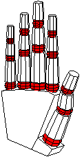
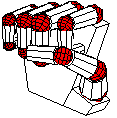
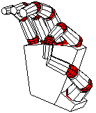
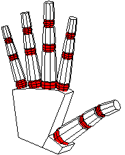
We can now have fun positioning the hand by adjusting the various rotation angles. The complete source includes definitions with alternatives that include the following views and more.